Showing posts with label Motive Power. Show all posts

Monday, 4 November 2019

Inspection of the ToyState Christmas steamer

Last July I bought a Toy State Christmas train set for only 10 euro's (see: Christmas in July). The engine itself did run well in my outdoor layout. It had no problem with the turnouts as long as it runs straight forward. However the engine made a howling sound. There were some suggestions on the forum that this could be a fan inside the locomotive. However as the locomotive was not able to pull all the cars from the set on the outdoor layout I suspect it could be a problem with the gears.
A test run on the track oval of the set did not show improvement; the engine could not pull all cars. Sometimes it stopped while the motor was running making. Running or standing still the engine makes the same howling sound.

So... time to open the engine!


The start; remove Santa figure and unscrew the screws at the bottom

Remove front bogie
Remove upper part

The switch can easily be removed


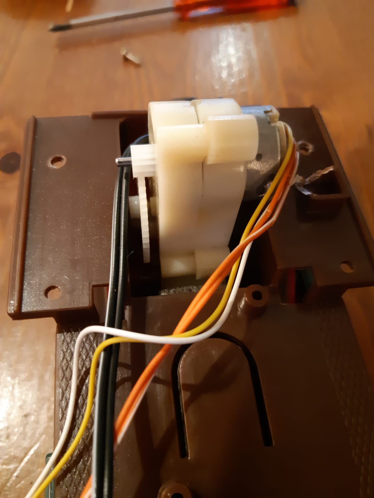
The motor is slides in the gearbox. It can be removed by pulling it out gently

The motor has a small gear wheel that connects to the gearbox

Backside view.
The connector cable that runs to the coal tender (with battery's).


Front view


View from top

After removing the motor (just gently pull it out of the gearbox) it looks like this:


Than remove front cylinders:


And remove gliders from the driving gear:


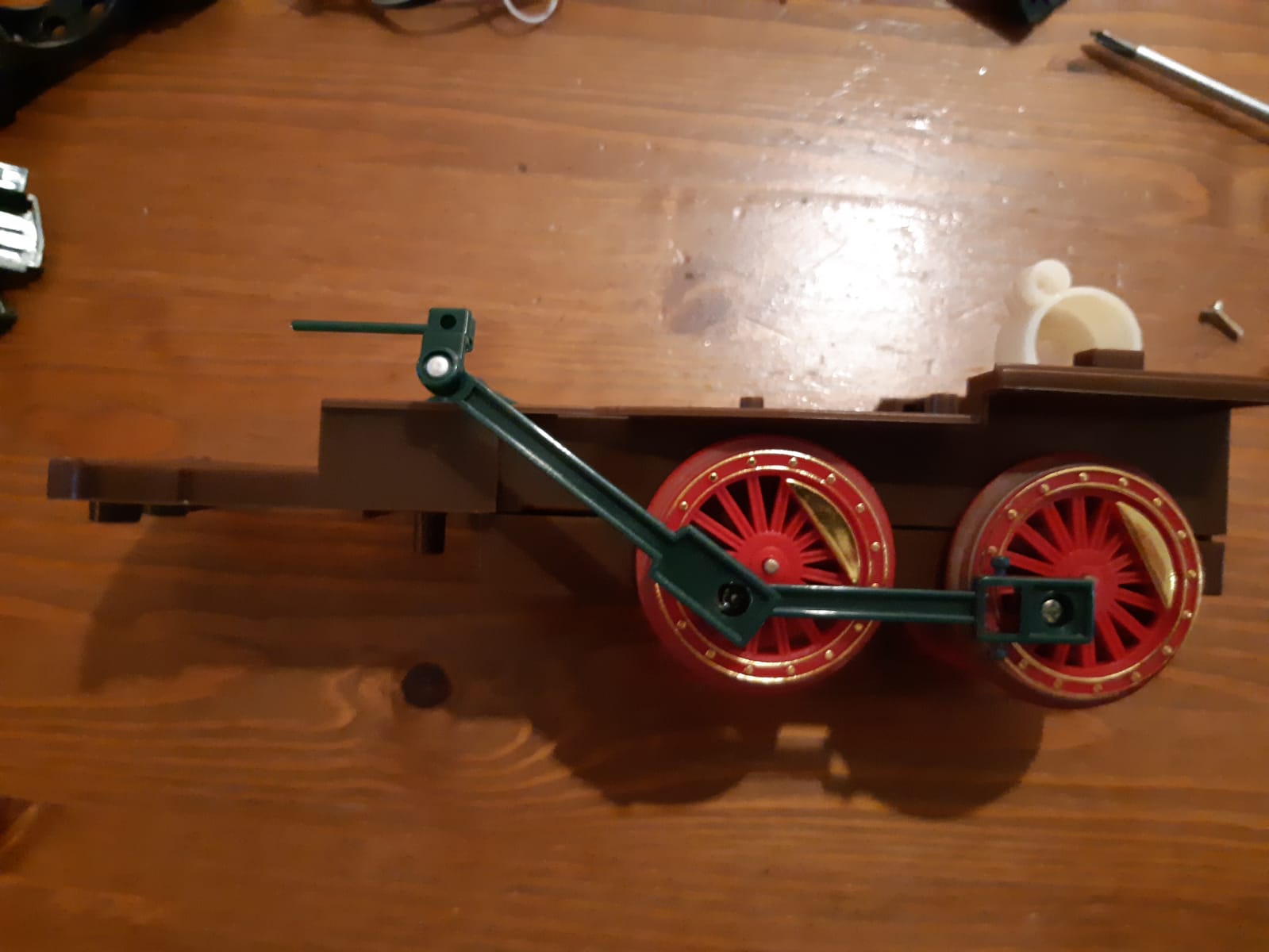
Removing the topside of the chassis shows the complete gearbox. It is fixed on the rear axle.
The gearbox itself is snapped together.


That's all...

So, we know how to dismantle the engine. Putting it together is just in the opposite order as shown above (and it works as these pictures were actually taken while putting the engine back together...).

Now... there was no fan or whatsoever present in the engine. Electric current flows from the connector cable to the switch at the side of the engine. From the switch two cables (orange and white) go to the motor. From the motor two cables (yellow and white) lead to the headlight. White cables connected to the switch make the polarity change (back and forward).
It is the gearbox that makes the howling sound. I believe the construction of the gearbox is not very solid and (worn out?) gears slide a bit over the axles (like the older Fleischmann locomotives did).
I could try to open it and see if I am right about that.  Perhaps I can replace the gearbox for a different one. Or do a total bash of the engine making something completely different from it and use the cars behind a standard LGB Stainz... Let's not forget the whole set costed 10 euro's. So we will see ;-)


Wednesday, 7 August 2019

RC control using the RailBoss Plus

Some while ago I dug up my trailer car with build-in RC unit and battery pack. It was still in one of the moving boxes after moving to this house more than 2 years ago.

The trailer car was constructed in 2011 using a ToyTrain freight car. The idea was to use the car to power and control my LGB locomotives. This way I did not have to convert the locomotives to battery power themselves. The locomotives can still be used for track power as I did not remove the sliding contacts and the contacts on the wheels. The locomotives can be powered and RC controlled using the plugs that are often used to power the coach interior lights

The RC controller is the RailBoss Plus controller from G-Scale Graphics (I just notice on their website it is no longer available as it is replaced by the newer RailBoss 4 unit). The transmitter and receiver are a 4 channel 2,4 Ghz set bought at HobbyKing. The battery is a 12 volts 2300 mAh battery pack (in this case from Conrad).
The battery can be charged by plugging a charging device in to the charging jack at the underside of the car. A little cable from the head side of the car connects it to the locomotive.
All electronics where nicely hidden out of side behind a plywood partition. So when the doors of the car are opened you can not notice the electronics. A switch in the partition could switch it off (to charging position) or on (to RC operation). The switch was easily accessible through the car sliding door.

Here is a little video on it from 2011:


Testing

The first thing that had to be replaced was the battery pack. Perhaps I had overcharged it after all those years but the fact was there was no power in it what so ever and it turned brownish at some spots... So a new battery was placed.
The second part that need replacement was the connector cable towards the locomotives. Back in 2011 I had chosen to use a little connector for aesthetic reasons. But I soon found out that these little connectors are not very sturdy and came loose after connecting and de-connecting locomotives several times. Also I had to construct an adapter cable from the LGB locomotive outlets to the mini connector. So now I made a simpler cable using standard hobby plugs that connect easily with the LGB plugs and sockets in (most) LGB locomotives. I had to construct 1 adapter cable to one of my Stainz locomotives as this model was issued with a different type of connector factory-wise.

So here it is now:


And here it goes:

July 25th 2019


And here is a little video of the running session:


-o-


Tuesday, 4 June 2019

Solar powered railcar Part VI

Testrun

Last night I made several test runs. After removing the useless diode (see part V) the car did had power enough to run its rounds. However the space between the front wheels (motorized axle) was a bit to wide causing the wheels to block in the curves. This was fixed by adjusting the distance between the wheels a bit.

First video: an early test run with flickering headlight (loose contact) and loosing one of the sliding doors! Sorry for the horrible sound...


Later that evening it finally runs well, especially considering the very moderate 1,5 volts power source! Again sorry for the sound...


Next (and final) step; windows and final detailing...


Solar powered railcar Part V


Some progress on the electrics. It is not my most favorite part as I lack the knowledge of it. It is trail and error for me.

As planned I connected the motor directly to the battery and added a small switch to turn the motor on and off. Due to the fact I misunderstood some good advise of a railway modeller on the Garden Railway Forum I had placed a diode (wrongly!) between the battery and the motor to avoid unwanted discharge of the battery. However this was a complete useless thing to do. The diode had no function on that spot at all... it only let the voltage drop with 0,7 volts, causing too low voltage to run.

The diode had actually made more sense between the panel and the battery cell ifI had chosen to charge the cell directly from the panel (which I did not as I let it charge using the connection on the board). When charged directly from the panel it is also better to use a Schottky diode instead of the BY diode I used as the Schottky has a way lower voltage drop (0,2 volts). Trail and error!
 
A 1,5 volts 2500 mAh battery cell is used (the original cell that came with the set was 600 mAh). Hopefully this will extend running time (but also will extend charging time). If not, or when charging takes way too long or don't charge at all, I will replace it with the 600 mAh again.Although I found the LED a bit too blue-isch I used it as headlight because, well... I had it.
Perhaps a bit of coloring will get a more warmer color and if not it can be replaced after all.


Overview; be aware: the green diode is REMOVED (see text)

LED in place

Switch for the LED glued in place. The motor switch will be next to it.

Overview on how the parts fit together
Charging up in the first June sun


- o -

Sunday, 19 May 2019

Solar powered railcar Part IV

Coach - work in progress

It has been a few weeks, so time for an update!

After building the chassis I started to build a coach. As said the model was loosely based on a Billard draisine that could be found on multiple French metre gauge and narrow gauge railway lines. I choose this simply because I liked the looks of it.
To keep is as light as possible the coach is build op from balsa sheets and cardboard (the backsides of paper notebooks). The coach will be attached to the chassis with small screws from underneath.

The in- and exterior were painted in a grey primer (Humbrol #1). The interior kept this grey color while the outside was painted in white and red livery. The model has sliding doors like some of these Billard draisines had. I left out the engine grille because, well... it is solar powered and not petrol powered after all ;-)

The pictures below shows the work the last weeks. The coach itself is for 90% done. I am still not sure what to do best with the wiring and I still need to figure out a removable roof (for access) that holds the solar panel.

But so far so good:


Priming the doors
 
Painting the coach in my 'neat and tidy' workshop...


- o -


Saturday, 13 April 2019

Solar powered railcar Part II

The motor

The Sol Expert kit was pretty straightforward to build. The instructions are simple and clear. You can choose between several gear ratios. The kit comes with a little wooden template to adjust the motor gear in different position depending on what ratio you choose.


The axle that came with the kit was a bit to thin for the LGB wheels I wanted to use so I made a spacer from a piece of  styrene tube. It works but I am not totally satisfied because one wheel has still a bit slack. Perhaps I will replace it in the future with a brass spacer. But for now it is good enough.


And the end result; motor, axle and wheels all in place and looking just fine.
Now I really need to figure out how to make a simple chassis...


- o -


Sunday, 7 April 2019

Solar powered railcar Part I


The original plan


Due to a few Youtube videos of solar powered garden trains I became fascinated by this idea and started an experimental solar powered model rail vehicle. After some (not to successful) searching on the internet for information on similar projects I realize I had to figure it out myself as much as I could. Because I am not very skilled in electronics I decided to buy on Conrad a “Solarhouse” and a motor with gearbox. Both kits are from Sol Expert (#40212 “Solarhaus” kit and #90015 “Universal getriebe”). See pictures below.

The house kit was bought because it has some electronic unit in it that charges the battery (or at least, that was what I thought it was, just keep reading...). 
This kind of electronic unit is certainly also present in most cheap LED garden lights of course, but mostly the electronic components in these have no visible codes or markings on it. As I want to examine what components can be used for making a similar unit myself, I wanted something with these codes still visible. I noticed this was the case on the Sol Expert kit.  
The kit itself is very straightforward (luckily); with a switch you can turn the LED on and off. I figured that I could replace the LED for the motor which will make the wheels spin and that would be it for me (I like things simple). No RC control desired at this moment, just want to let it work for now. The Sol Expert 0,6 – 6 volts motor is designed to run on the solar charged 1,2 volts battery. If I keep the model as light as possible, it will work (I hoped).


The second plan (after some wise advise)

Fortunately I received some very helpful advise on the Garden Railway Forum that made me understood the electronics a bit more. There is NO special charger unit in it as I had guessed. The solar panel just charges the NiMH battery. The two components are a LED driver that shuts off the LED when the voltage drops below a certain point, and an inductor.
The advise was to run the motor straight off the battery and not to replace the LED with the motor hence the chip has some current limiting function.
So, the plan is now to keep the electronic unit as it is (it will be a headlight for the railcar) and connect the motor directly to the battery together with an on/off switch. See the drawing schedule below.

Next, figuring out how I build it on some sort of base or chassis and what it would look like...
To be continued!


Sol Expert Solar House electronics #40212
Sol Expert #90015 Gearbox and motor
LED driver

Inductor
The first setup
It works!

The plan...


- o -


Saturday, 2 February 2019

December 2018 - snow!!

Snowy pictures on December 16th 2018